
The timing diagram for the negatively triggered JK flip-flop: The truth table for a negatively triggered JK flip-flop: The JK flip-flop is usually negative edge triggered.

If J and K are both 1, the output is inverted. If J and K are both 0, the output stays the same as it was before. J corresponds to a "set" signal, and K corresponds to a "reset" signal. The JK flip-flop has two inputs, labeled J and K. Timing diagram for the positive edge triggered D flip-flop: (↑ indicates a rising edge on the clock pulse X indicates that it has no effect on outcome)

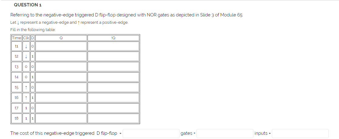
The truth table for a positive edge triggered D flip-flop: The D flip-flop is usually positive edge triggered. The D (Data) flip-flop has an input D, and the output Q will take on the value of D at every triggering edge of the clock pulse and hold it until the next triggering pulse. There are several types of flip-flops but the two most important kind are the D and J-K flip-flops. Truth Table for CLR and PRE (active low) PRE The symbols used for clear and preset (the bubble indicates an inverted signal): The CLR and PRE signals can be asserted any time and don't have to be edge triggered they will override any other inputs, including the clock. These inputs are typically inverted, so they are active when the input signal is low ( Active Low Input). Many flip-flops will also have a clear (CLR) and preset (PRE) terminal. The symbols used for positive and negative edge triggering on flip-flops:

Flip-flops are edge triggered they either change states when the clock goes from 0 to 1 (positive/rising edge) or when the clock goes from 1 to 0 (negative/falling edge). Because the state of a flip-flop often depends on the previous state of a circuit (for example, the output of one flip flop may be the input to another), and because each flip-flop and logic gate needs a certain amount of time to switch its output, we usually clock the devices, that is, we synchonize all the flip-flops to change states at the same time with a clocked pulse.


 0 kommentar(er)
